Gallery

Collage of starter models

Time to bolt!It’s Time to bolt!

caitlin-mods1

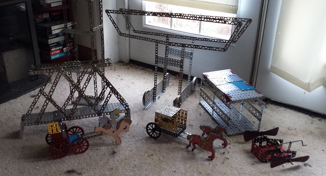
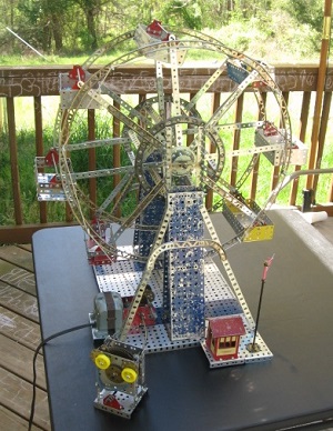
One day I came home from work, and discovered that my daughter had been building with the Erector set. A few days earlier she had asked me about using it. I suggested that she start with some of the simpler models designed for the smaller sets, like the 1 or 2 level sets from the Renaissance era. (The bulk of my Erector is Renaissance-era Class-II.) This is exactly what she did, and she even made up a few freelance models. A group portrait of these models is featured above.

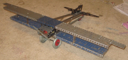
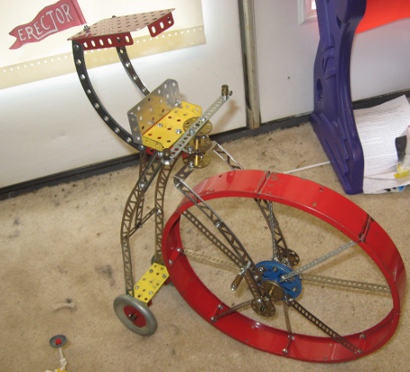
From left to right to right we have a truss bridge, a four-wheel horse drawn carriage, an elevator (background), and mobile cargo crane, a two-wheel horse drawn carriage, a covered bridge, and a… whirligig flying machine thing. We never really decided exactly what to call that thing.

As you can see, she made use of the customized carousel horse parts that were created for an earlier model.

caitlin-mods2

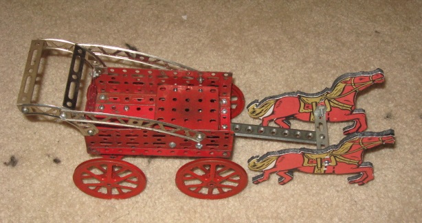
This is one she made a little later, after looking at some photographs of horse-drawn sleds. She really likes the carnival horse parts, both official and custom.

erectorRV

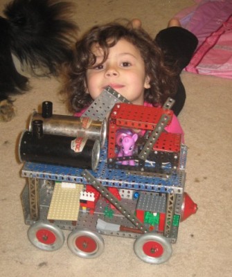
This one dates from a bit earlier, and it’s supposed to be a “steampunk recreational vehicle.” It’s supposed to be powered by the two steam boilers on the roof. I did the actual building of this one, but she designed it. She made up a few drawings (blueprints!) which I used to build this. She then pimped out this ride with furnishings made from Legos, and sent some Little Ponies on a cross-country adventure.

She’s a Lego master builder, who dabbles in Erector and other building toys. Damn, I’m proud of that girl!

Hillman Ferris Wheel

Time to bolt!It’s Time to bolt!

hfw-1

Ferris wheel rides have been a favorite modeling subject for metal construction toy users for many years. Erector and Meccano have both provided specialized kits and plans for Ferris wheels over the years, and Marklin made a specialty kit of the Wiener Riesenrad that is simply spectacular! However, a Ferris wheel is a deceptive piece of engineering. It is very simple in design, but the wheel and the baskets have to be very well balanced, and that is where the challenge lies.

My contribution to this tradition is a number I called the Hillman Ferris Wheel. I so named it because the spokes of the wheel were made using mending strips manufactured by the Hillman Group. These parts are made from an aluminum and steel mix that is supposed to be flexible yet strong, and are intended to be used in home repair projects. They look a lot like Maccano strips, so I wanted to see how they got along with Erector. In short, they did just fine. By combining 2-3 mending strips of different sizes, I was able to make the Ferris wheel’s spokes exactly the length I wanted, without having to bow or contort any other parts.

Ferristhumb

The base for my design was the one that was featured with the Renaissance-era “10 ½ Amusement Park” set. A slightly smaller and simpler version of this model could also be built using the “7 ½ Engineer’s Set” of the same era. I used elements of both models, along with some ideas from the Class-III era.

The model follows the classic model fairly closely in terms of core, structural design, but I put in some additional tweaks. For example, there is a secondary support wheel within the main wheel, made from Class-III perforated curved beams, to prevent the spokes from bowing, and to help keep the weight centered. I also built my wheel with eight baskets instead of four, simply because I had sufficient parts. Two of the baskets are made from Class-III parts, while the other six are Class-II.

hfw-2
From a different angle.

The engine is a standard configuration of the A49 motor. I opted for slow instead of speedy, in the interest of power. I also think that if I had used one of the speedy configurations, the passengers of the Ferris wheel, Smurf figurines in this case, would end up being catapulted around the room. I tried a number of different pulley and chain configurations, but never found one I really liked. In the end, I connected the output pulley directly to the main wheel of the Ferris wheel. This resulted in a slow, but fairly steady ride. The last time I was on a Ferris wheel, it wasn’t very fast. But then again, that was the one on Navy Pier in Chicago, and it’s pretty darn big! It’s not as big as the monsters in London or Austria, but it’s no slouch. Such a ride wouldn’t be fast.

The contraption with the goofy, rotating eyes, is simply a sight gag. In keeping with the amusement park theme, it could be the door to a fun house, or something of the sort. The “derpy” effect is achieved by means of the partial large gear (OI) that was a key component of the famous parachute jump model. This visual guffaw borrowed some power from the A49 by means of an OE flexible coupling.


MP4 video, 21 seconds.


Other resources:

Crank Action models

Time to bolt!It’s Time to bolt! This article originally appeared in my earlier blog site.

cranktriptic

These three models were designed to be simple enough for my daughter to assist. At this time, she was only six, so Erector was still a little beyond her age bracket.

CrankHammerCrane

This simple hammerhead-style crane features a swiveling top, and a crank-driven lift. The model was very light weight, so it couldn’t lift very much. But that didn’t stop my daughter from having great fun with it.

Bigbiplane

This airplane model is something I came up with after looking at some illustrations of heavy planes and bombers from the World War I era. They tended to have wings that were proportionally too large for their fuselage, and they were often quite slow. The engines of the time couldn’t deliver the thrust of later ones, so a larger lifting surface was provided to make the most of whatever power the engine could provide. Improvements in engine technology eventually made this issue moot, resulting in heavier planes that were more compact in design, faster, and more stable.

This model was equipped with a turning propeller, that was attached to a strong rubber band going through the body of the plane. It didn’t use a crank, but the propeller could be “wound up,” then allowed to spin freely until the band ran out of torque. The result was akin to those gliding balsa wood planes with wind-up propellers. Of course, this model couldn’t really fly.

CrankCopter

This helicopter was a big hit with my daughter. It’s supposed to represent one of those heavy, cargo-carrying helicopters that are sometimes seen around seaports. Or, the military variants that deliver soldiers and supplies to an inaccessible area. It’s not clear in this picture, but a crank on the opposite side of the model drove a pair of miter gears within the body of the helicopter, and a sprocket. The miter gears drove the main rotor, while the sprocket and chain turned the steering rotors in the tail.

Incidentally, this was the first time I made real use of a sprocket and chain in a model. Sprockets and chains appeared sparingly throughout Erector’s history, as an alternative to pulleys and bands. There was some evidence that chains were more efficient at transferring power than pulley bands, but even so, they were never promoted much. I suspect the reasons were cost (chains were more expensive to make than pulleys), and maintenance (changing the length of a chain is a real chore, and without the right tools, breaks are a given). At any rate, I made very good use of chains in a future model.

The chains and sprockets I used were reproductions of the Class-III era parts from the early 1970’s, and were acquired from Joel Perlin.

Penny Farthing

Time to bolt!It’s Time to bolt! This article originally appeared in my earlier blog site.

pennyfarthing


We seek information…
You won’t get it!
By hook, or by crook, we will!

This quickie model was something I put together largely to experiment with the CS boiler segments, and to try a specific building technique. The model is a very simple one, and is supposed to represent an old penny-farthing style bicycle (below, far left). Construction took just over an hour. Most of that time was taken up by the spokes in the main wheel.

pf-triptik

These old bikes aren’t very common today, but I’ve seen some from time to time. The owner of a local bike shop rides one during the annual Forth of July parade. The most famous penny-farthing in history is perhaps the one from the British television series “The Prisoner.” (center)

The true penny-farthing had only two wheels, but my model has three so that it wouldn’t keep falling over. The size was such that one of my daughter’s Barbie dolls could sit comfortably on the seat and “ride” around the play room. Sadly, the awning over the seat kept getting in the way, so it was removed in short order.

The large wheel is made from a set of CS curved boiler sections, which is too thick for a true penny-farthing. I guess this would have to be a “mountain bike” variant (above, far right). Anyway, the spokes were made from “I” perforated strips and a pair of CR hub turret plates. I have some other ideas for models that feature a spoked wheel based on the CS sections; this model was my proof of concept. The combination of parts worked perfectly.

Real penny-farthings are steered by a direct steering bar on the main wheel, just as with modern diamond-frame bicycles. This model can be “steered” the same way, at up to a 70-degree angle. I understand that a real penny-farthing has a similar limitation. I suspect that taking a turn too tightly on one of these things would be a painful experience!

This was a simple, but fun little model. The biggest problem with it was keeping the wheel fork tight. The seat and back wheel carriage had a tendency to “kick out” behind the large wheel, and required frequent tightening. If I ever make this model again, I’ll use a pair of 8-32 wing nuts, or a pair of thumb-tap screws, to hold the wheel fork.