
![]() It’s Time to bolt!
It’s Time to bolt!
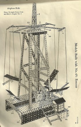
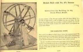
Ferris wheel rides have been a favorite modeling subject for metal construction toy users for many years. Erector and Meccano have both provided specialized kits and plans for Ferris wheels over the years, and Marklin made a specialty kit of the Wiener Riesenrad that is simply spectacular! However, a Ferris wheel is a deceptive piece of engineering. It is very simple in design, but the wheel and the baskets have to be very well balanced, and that is where the challenge lies.
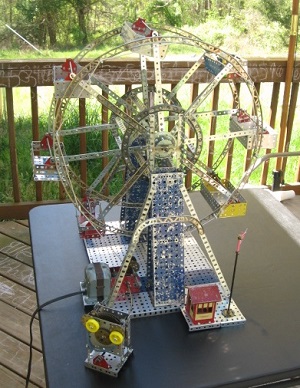
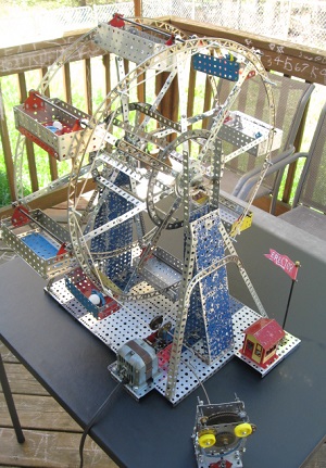
My contribution to this tradition is a number I called the Hillman Ferris Wheel. I so named it because the spokes of the wheel were made using mending strips manufactured by the Hillman Group. These parts are made from an aluminum and steel mix that is supposed to be flexible yet strong, and are intended to be used in home repair projects. They look a lot like Maccano strips, so I wanted to see how they got along with Erector. In short, they did just fine. By combining 2-3 mending strips of different sizes, I was able to make the Ferris wheel’s spokes exactly the length I wanted, without having to bow or contort any other parts.
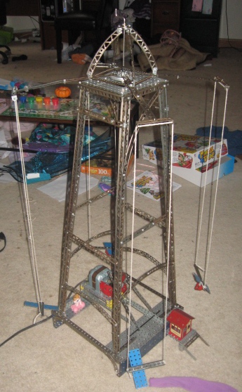
The base for my design was the one that was featured with the Renaissance-era “10 ½ Amusement Park” set. A slightly smaller and simpler version of this model could also be built using the “7 ½ Engineer’s Set” of the same era. I used elements of both models, along with some ideas from the Class-III era.
The model follows the classic model fairly closely in terms of core, structural design, but I put in some additional tweaks. For example, there is a secondary support wheel within the main wheel, made from Class-III perforated curved beams, to prevent the spokes from bowing, and to help keep the weight centered. I also built my wheel with eight baskets instead of four, simply because I had sufficient parts. Two of the baskets are made from Class-III parts, while the other six are Class-II.
From a different angle.
The engine is a standard configuration of the A49 motor. I opted for slow instead of speedy, in the interest of power. I also think that if I had used one of the speedy configurations, the passengers of the Ferris wheel, Smurf figurines in this case, would end up being catapulted around the room. I tried a number of different pulley and chain configurations, but never found one I really liked. In the end, I connected the output pulley directly to the main wheel of the Ferris wheel. This resulted in a slow, but fairly steady ride. The last time I was on a Ferris wheel, it wasn’t very fast. But then again, that was the one on Navy Pier in Chicago, and it’s pretty darn big! It’s not as big as the monsters in London or Austria, but it’s no slouch. Such a ride wouldn’t be fast.
The contraption with the goofy, rotating eyes, is simply a sight gag. In keeping with the amusement park theme, it could be the door to a fun house, or something of the sort. The “derpy” effect is achieved by means of the partial large gear (OI) that was a key component of the famous parachute jump model. This visual guffaw borrowed some power from the A49 by means of an OE flexible coupling.
MP4 video, 21 seconds.
Other resources: